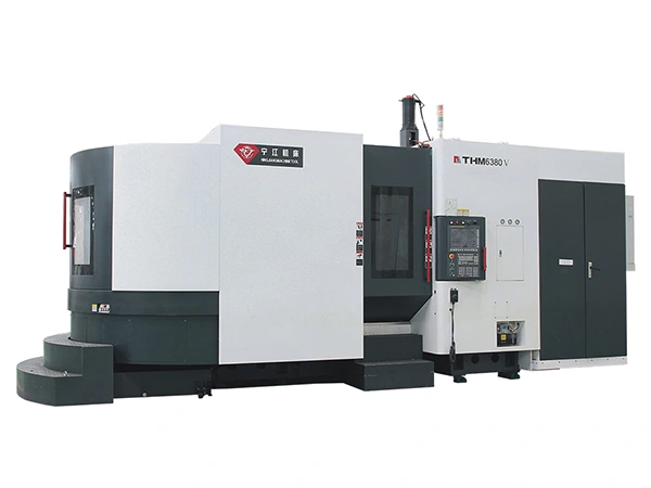


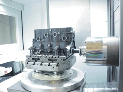
5-Axis Machining Center with 45° Tilt Head
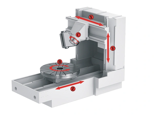
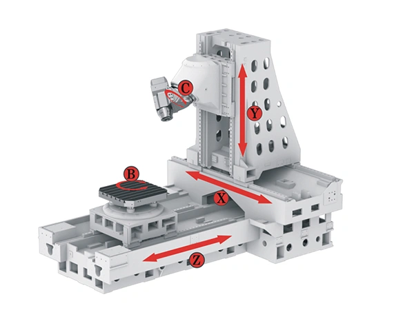
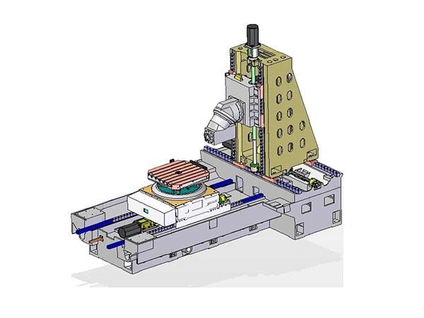
The 5-axis machining centers with a 45° tilt head use a T-shaped layout, with the column moving on the X axis, the spindle head travelling vertically on the Y axis, and the table advancing along the Z axis. Table sizes range from 650 to 1200 mm, and a vertical-table configuration is available when an upright orientation is required.
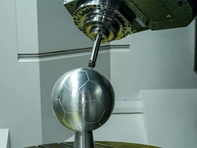
The spindle head tilts 45°, allowing vertical and horizontal machining in one setup. Continuous rotary movement can be provided through a high-precision worm-gear rotary table. When higher responsiveness and zero mechanical backlash are needed, a torque-motor direct-drive rotary table can be selected. A torque-motor direct-drive milling-and-turning table is also available for applications that require both operations.
 THM63160V
 THMD63100V
These 5-axis machining centers control movement along the X, Y, Z, B and C axes, enabling full 5-axis simultaneous machining. Spindle speeds can be configured at 7,000, 10,000, 12,000 or 18,000 r/min depending on the process requirements. Their configuration supports the machining of complex components used in automotive, marine power systems, energy equipment and mold manufacturing.
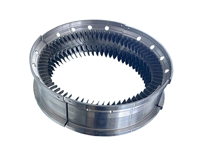
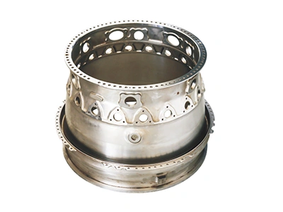
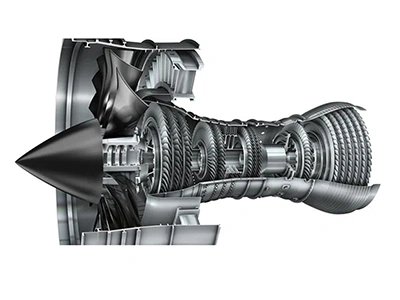 Power Industry
 Automotive Industry
 Shipbuilding Industry
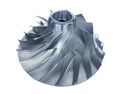
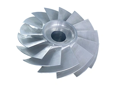
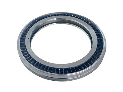
- Material: Aluminum alloy
- Size: Ø274 × 109 mm
- Machining Cycle: 706 minutes
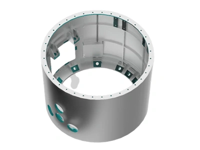
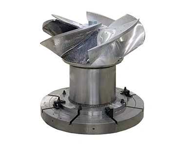
- Material: Aluminum alloy
- Size: Ø740 × 510 mm
| Model | | | | |
| Worktable size (mm) | Ø800 /800×800 | Ø1000 /1000×1000 | Ø1250 /1250×1250 | Ø1600/Ø1800/Ø2000 |
| Max. worktable load capacity (kg) | 2000 | 2000 | 2000 | 2000 |
| X-axis travel (mm) | 1200/1400 | 1600 | 1600 | 2100 |
| Y-axis travel (mm) | 1000/1200/1400 | 1000/1200/1400 | 1000/1200/1400 | 1250/1600 |
| Z-axis travel (mm) | 1100/1400 | 1600 | 1600 | 2100 |
| B-axis swing range (°) | n×360 | n×360 | n×360 | n×360 |
| C-axis rotation range (°) | -15 to +195 | -15 to +195 | -15 to +195 | -70 to +180 |
| Spindle speed (r/min) | 20–15000 | 20–15000 | 20–15000 | 20–10000 |
| Positioning accuracy (X/Y/Z) (mm) | 0.008 | 0.008 | 0.008 | 0.008 |
| Repeatability (X/Y/Z) (mm) | 0.004 | 0.004 | 0.004 | 0.004 |
| B-axis positioning accuracy (″) | 8 | 8 | 8 | 8 |
| B-axis repeat positioning accuracy (″) | 4 | 4 | 4 | 4 |
| C-axis positioning accuracy (″) | 10 | 10 | 10 | 10 |
| C-axis repeat positioning accuracy (″) | 5 | 5 | 5 | 5 |
The spindle assembly uses a 45° tilting head that switches between vertical and horizontal machining, with the spindle mounted on this tilting axis to rotate along the C-axis for angled operations. The spindle uses a built-in motor, so the drive power goes directly into the spindle and stays steady during cutting. The bearing temperature is tracked so the spindle stays steady and the machining accuracy doesn’t drift during long cuts.

The X, Y and Z axes use servo-driven linear guide rails paired with precision ball screws. The axes can move at high speed, up to 40 m/min, while still keeping positioning steady, and the low-speed motion stays smooth without any crawling. The linear guides use a centralized lubrication system that keeps friction down and reduces wear, which helps the machine hold its accuracy over long periods of use.