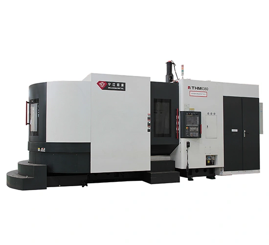


Horizontal Machining Centers
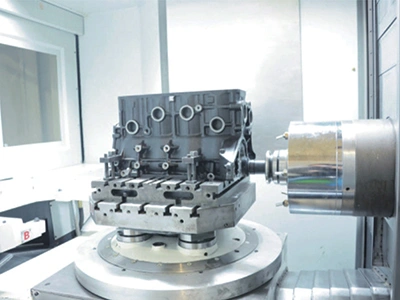
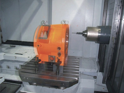
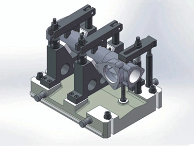
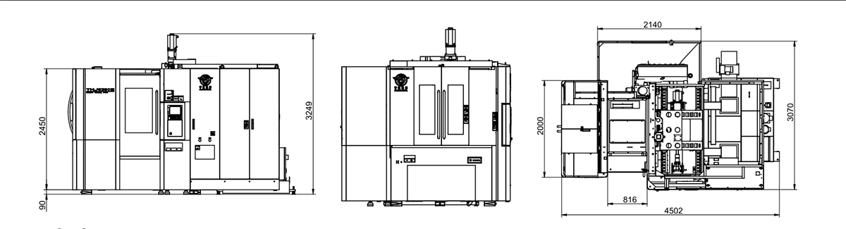
Horizontal machining centers with 500-1250 mm worktables use a T-shaped monolithic bed that provides the rigidity needed for heavy-duty cutting. The T-shaped bed distributes cutting forces evenly, reducing deformation during heavy cuts. By keeping heat buildup and vibration under control, the structure helps the machining center maintain stable accuracy throughout long operations.
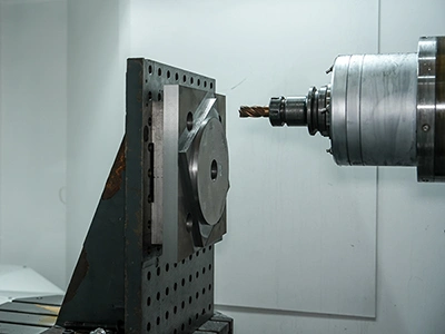
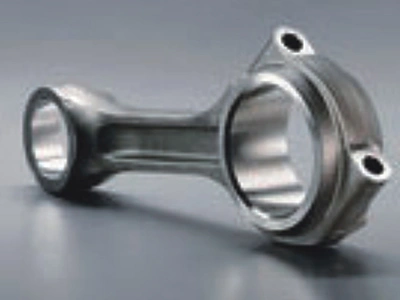
Once clamped, the workpiece can undergo drilling, boring, reaming, tapping, milling and rough-to-finish contour machining without additional setups. These capabilities suit box-type components used in shipbuilding, automotive production, hydraulic and wind-power equipment, machine tool frames, mold bases and railway assemblies. These horizontal machining centers are built around a design approach that values precision, consistent efficiency, reliable performance, environmental responsibility and reasonable long-term upkeep, making them suitable for continuous production environments.
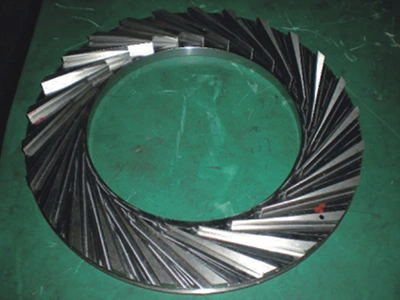
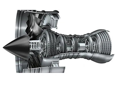 Power Industry
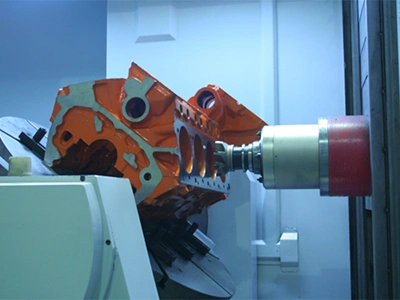
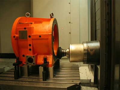
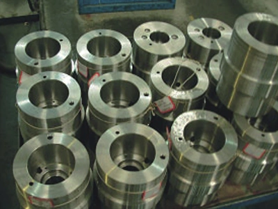
 Marine Engineering
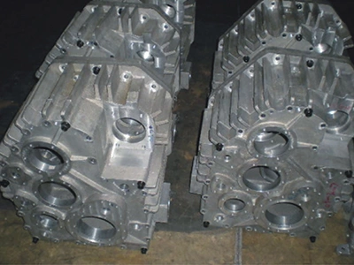
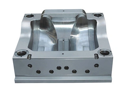 Mold Manufacturing
| Model | | | | | | |
| Pallet Worktable | ||||||
| Pallet size (L× W) (mm) | 500×500 | 500×500 (optional: 500×630) | 630×630 | 800×800 | 1000×1000 | 1250×1250 |
| Pallet indexing (°) | 1°×3601°×360 (end-tooth plate indexing) | 1° × 360 (end-tooth plate indexing) 0.001° × 360000 (continuous indexing) | ||||
| Max. pallet rotation speed (r/min) | 12 | 8 | 8 | 8 | 5 | 5 |
| Max. pallet load (kg) | 800 | 800 | 1000 | 2000 | 2500 | 3000 |
| Max. Workpiece Diameter swing diameter (mm) | Ø850 | Ø750 | Ø950 | Ø1250 | Ø1650 | Ø1900 |
| Number of pallets (APC) (pcs) | / | 2 | 2 | 2 | 2 | 2 |
| Pallet change time (s) | / | 16 | 16 | 20 | 25 | 35 |
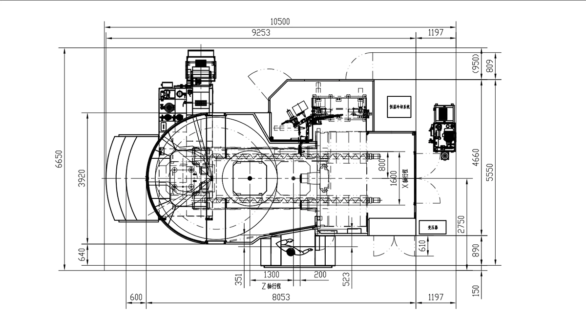
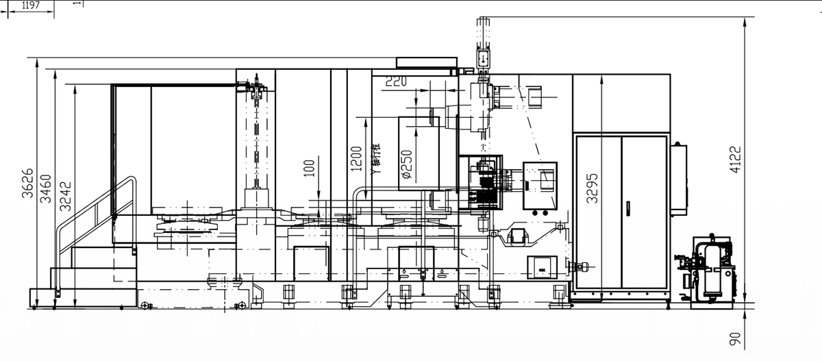
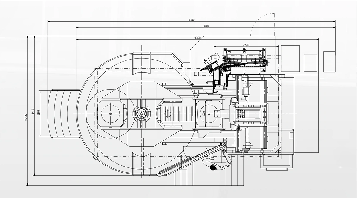
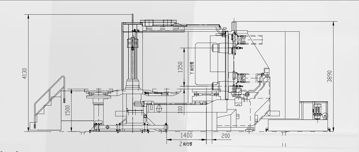
| Main Travels | ||||||
| X-axis travel (column) (mm) | 800 | 900 | 1000 | 1300 | 1600 | 1700 |
| Y-axis travel (spindle head) (mm) | 750 | 700 | 800 | 1000/1200 | 1200 | 1350 |
| Z-axis travel (worktable) (mm) | 800 | 900 | 900 | 1100 | 1300 | 1360 |
| Spindle centerline to pallet surface distance (mm) | 100–850 | 50–750 | 50–850 | 50–1050/1250 | 100–1300 | 100–1450 |
| Spindle nose to pallet center distance (mm) | 100–900 | 150–1050 | 150–1050 | 200–1300 | 200–1500 | 240–1600 |
| Spindle | ||||||
| Spindle taper | No.50 | No.50 | No.50 | No.50 | No.50 | No.50 |
| Spindle speed (r/min) | 20–6000 (standard) | 20–6000 (standard) 20–8000 (optional) | 20–6000 (standard) 20–8000 (optional) | 20–6000 (standard) 20–8000 (optional) | 20–6000 (standard) 20–8000 (optional) | 20–6000 (standard) 20–8000 (optional) |
| Speed range selection | Fully programmable speed range | |||||
| Spindle motor (kW) | 15/18.5 | 18.5/26 | 18.5/26 | 30/37 | 30/37 (optional: 37/45) | 30/37 |
| Max. spindle torque (N·m) | 143/236 | 310/525 | 310/525 | — | 307 or 1288 (with reducer) Optional: 374 or 1496 (with reducer) | |
| Tool Magazine | ||||||
| Tool capacity (tools) | 30 (optional: 40, 60, 80) | 40 (optional: 60, 80, 100, 120) | ||||
| Tool holder type | BT50 (optional: ISO50, SK50) | BT50 (optional: ISO50, SK50, JT50) | ||||
| Max. tool diameter (mm) | Ø110/Ø220 | Ø125 (with tool in adjacent pocket) Ø250 (without tool in adjacent pocket) | ||||
| Max. tool length (mm) | 450 | 450 | 550 | 550 | 600 | 600 |
| Max. tool weight (kg) | 25 | 25 | 20 | 25 | 25 | 25 |
| Tool-to-tool change time (s) | 3.5 | 3.5 | 3.5 | 4.5 | 4.5 | 4.5 |
| Tool selection method | Random, bidirectional | Fixed position, bidirectional tool selection | ||||
| Axis Drive System | ||||||
| Feed speed range (m/min) | 0–20 | 0–20 | 0–20 | 0–20 | 0–20 | 0–20 |
| Rapid traverse speed (m/min) | 36/30/36 | 45 | 45 | 40 | 40 | 40 |
| Servo motor power (X, Y, Z) (kW) | 3 | 4 | 4 | 6 | 6 | 6(X,Y)/7(Z) |
| B-axis servo motor power (kW) | 1.4 | 3 | 3 | 3/4 | 3/4 | 3/4-axis (with continuous indexing) |
| Position feedback (X/Y/Z/B-axis) | Encoder | Encoder (linear scale) | ||||
| Min. Resolution (X/Y/Z) (mm) | 0.001 (optional: 0.0001 mm) | |||||
| Min. B-axis resolution (°) | 1 | 0.001 (optional: 0.0001 mm) | ||||
| Machine Accuracy | ||||||
| Positioning accuracy (X/Y/Z) (mm) | 0.01 | 0.008 | 0.008 | 0.008 | 0.008 | 0.008 |
| Repeatability (X/Y/Z)(mm) | 0.005 | 0.004 | 0.004 | 0.004 | 0.004 | 0.004 |
| B-axis indexing accuracy (″) | 8 | 8 | 8 | 8 | 8 | 8 |
| B-axis repeat indexing accuracy (″) | 4 | 4 | 4 | 4 | 4 | 4 |
| Geometric accuracy | Precision grade: GB/T 20957.1-2007 Standard grade: GB/T 18400.1 | |||||
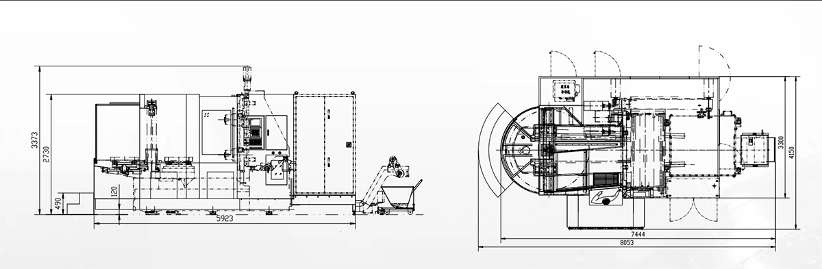
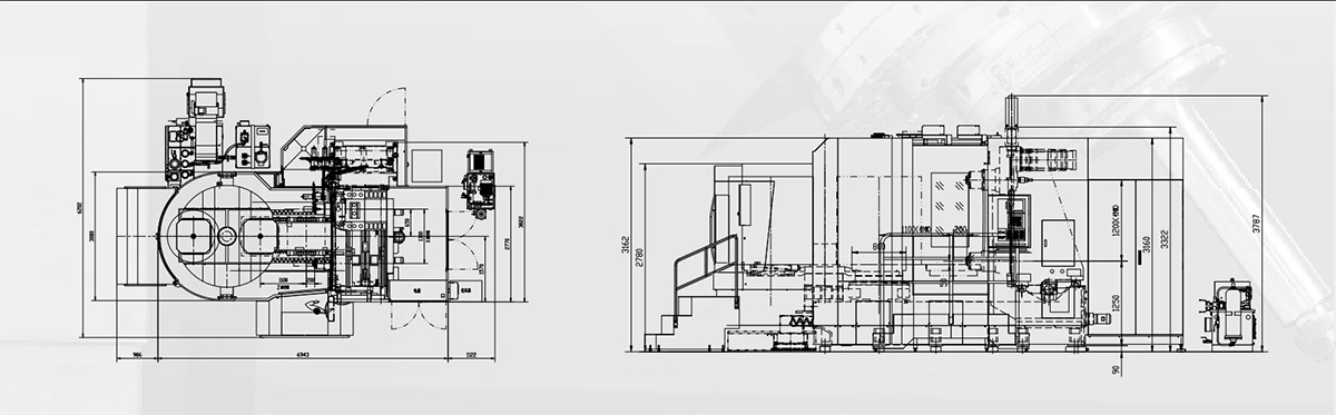
| Installation Data | ||||||
| Machine weight (t) | 12 | 21 | 22 | 24 | 32 | 38 |
| Total installed power (kVA) | 40 | 60 | 60 | 100 | 100 | 110 |
| Power supply | 380V/50Hz/3-phase | |||||
| Required compressed air pressure (MPa) | 0.6 | 0.6 | 0.6 | 0.6 | 0.6 | 0.6 |
| Required compressed air flow rate (L/min) | 350 | 350 | 380 | 380 | 380 | 380 |
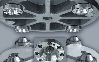
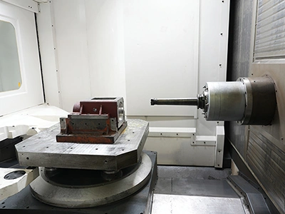
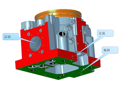
The four-point kinematic positioning structure, combined with hydraulic clamping, provides high positioning accuracy and strong locking force.
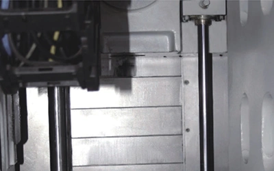
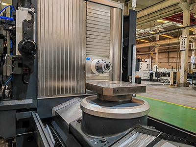
The spindle head uses a hydraulic counterbalance system to support vertical (Y-axis) movement. The hydraulic counterbalance system eases the load created by the spindle head’s weight, allowing the Y-axis to move more smoothly and stay accurate throughout long machining operations.
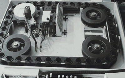
The ATC is built in two configurations. One uses a mechanical-arm magazine to hold and change tools, while the other relies on a swing-arm mechanism to carry out the tool exchange. The mechanical-arm uses two grippers to pick up and replace tools in a random sequence, and it can handle tools that weigh up to 25 kg without affecting the changeover motion. The spindle uses a No.50 taper interface and works with standard holders such as BT50, ISO50, SK50 and JT50. The tool magazine operates with a chain-type drive and is supplied with a 40-tool capacity as standard. Optional configurations include 60, 80, 100 and 120 tools to meet different production requirements.
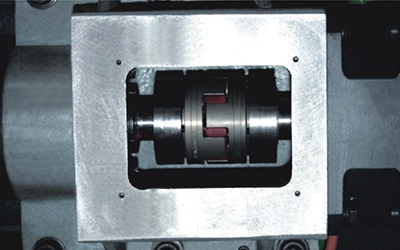
The servo motor is connected directly to the ball screw through a precision coupling. The precision coupling minimizes deformation or lateral shift in the ball screw, even under heavy load, allowing the axes to keep their positioning accuracy and improving the overall machining result. The reduced mechanical stress also contributes to longer service life.
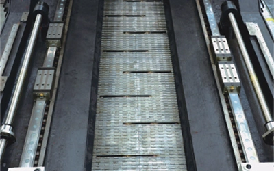
Double-screw chip conveyors (THM6380, THM6363A, THM6350 and TH6350) and chain-type conveyors (THM63100 and THM63125) are used to clear chips from the cutting area. The steep-angle guideway covers guide chips into the side channels, where the conveyors move them out of the working zone for smoother, more consistent evacuation. Different conveyor styles are selected according to the model and chip-handling requirements of each horizontal machining center.
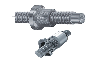 Ball Screw
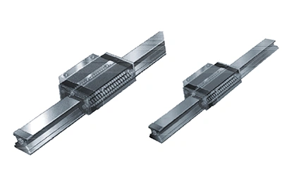 Linear Guideways
High-quality linear guideways and ball screws from THK and NSK are used to support the accuracy and long service life expected in precision machining. Both components are preloaded to remove backlash and maintain load capacity in every direction. The low-friction design allows fast axis movement, smooth low-speed travel and accurate positioning, even when the Z-axis is cutting under heavy load. Each linear guideway is equipped with an independent automatic lubrication system to ensure consistent performance over time. The mounting surfaces for the guideways are hand-scraped to achieve higher installation accuracy and stable motion during machining.